|
.png)
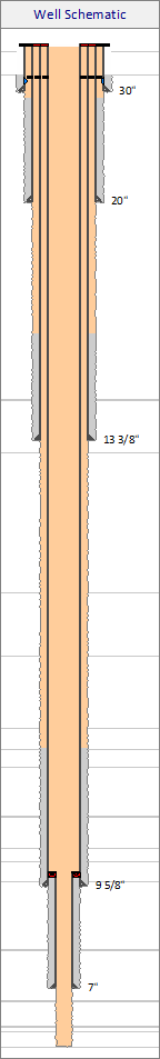
 The well schematic editor is re-sizable (drag bottom-right corner with the mouse). Alternatively, more space for a grid may be created by collapsing one or more sub-grids (External, Internal, Ancillary). When hovering the mouse below the casings grid, a handle will become visible that may be dragged to enlarge the casings grid. The well schematic editor is re-sizable (drag bottom-right corner with the mouse). Alternatively, more space for a grid may be created by collapsing one or more sub-grids (External, Internal, Ancillary). When hovering the mouse below the casings grid, a handle will become visible that may be dragged to enlarge the casings grid.
|
.png)
|
Column properties
|
|
In addition to the properties common to all columns (width, visible, etc), a virtual horizontal scale can be specified for the well schematic. This scale is used for drawing the casing strings. Each casing is drawn at its own index. The smallest casing size has index 1 with the largest casing having the highest index. Hence to draw the schematic narrower or wider, the horizontal scale must be modified.
To maintain consistent sizing of casings when drawing multiple well schematics to show an operational sequence (i.e. hiding smaller casings not yet run), ghosting may be applied.
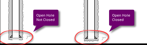
With the shoe and open hole not visible, the "casing" effectively becomes a tubing string.
Two casings of the same OD, where the MD ranges do not overlap, will be drawn on the same horizontal index. This is useful for strings with a gap (e.g. after section milling a casing).
|
|
.png)
|
Casing strings
|
|
Define casing strings and open hole drawing here. Depths are shown (or input) in the currently active Depth Unit. Label (font) properties may be set with the Properties button. Most items are self-explanatory but checking 'Open Hole' closed will draw a closed bottom as shown below.
|
|
.png)
|
External (annular) items
|
|
Specify items for the casing annulus. If the casing is not drawn (i.e. open hole only) the External items are drawn to fill the Open Hole.
The Type field is merely a label to make the data more readable. It has no further function. Label (font) properties may be set with the Properties button.
MD's may be beyond the MD's of the associated casing string / open hole range.
|
|
.png)
|
Internal items
|
|
Specify items inside the casing (content). As for Externals, the Type field is merely informational. Note that labels (if visible) are drawn centered and vertically oriented inside the Internal item. Label (font) properties may be set with the Properties button.
MD's may be beyond the MD's of the associated casing string / open hole range.
Internal item MD's may overlap. This may be useful when drawing sequences. For example: two internal items may be specified (mud and cement) where one (mud) fully overlaps the other (cement).
|
|
.png)
|
Ancillary items
|
|
A variety of ancillary items are pre-defined that can be drawn with a casing string. Currently, the following ancillary types are pre-defined:
•Undefined
•Hang-off point
•Hanger (wellhead)
•Hanger and packer (wellhead)
•Liner hanger
•Liner hanger and packer
•Stage collar
•Bridge plug *
•Packer *
•Perforations
•Casing perforations
•Screens
•Safety valve *
•Gas lift valve
•Fish *
•Collapse (casing) *
•TA cap
•Vented TA cap
•ESP (Electric Submersible Pump)
•SSD (Sliding Side Door) *
•Check valve (down) *
•Check valve (up) *
•Other
Item and label (font) properties may be set with the Properties button.
|
Drawing sequence
To get a the best result when composing a well sketch, it is good to understand how the drawing is built. Casings and their associated open hole are drawn from the largest size to the smallest size (i.e. smaller casings and their associated open hole are drawn over the larger size casings.
•The external item are drawn to fill a rectangle from MD From to MD To vertically and from the left to the right index value of the open hole (imaginary scale as described above).
•Next, the internal items are drawn for the same MD range but using the casing left and right index values.
•Certain type of ancillary items are drawn before the casing. These items are marked with an * in the list above.
•The casing and open hole are drawn (each if visible)
•The remain type of ancillary items are drawn.
Note that External and Internal items may be specified with MD From and MD to beyond the MD From and MD To of the casing string. In certain cases this may be useful to fill up gaps.
Any Internal (or External without the casing shown) will automatically have its label drawn inside; centered and oriented vertically. This is useful for labeling (open hole) fluids, cement plugs etc.
Certain Ancillary items (e.g. bridge plugs) have a relatively short length (e.g. 3m / 10 ft). On a well sketch for a deep well, this length would reduce to merely a line when scaled with the well. Such items are therefore drawn with a minimum height. Sometimes this may lead to overlap (e.g. two bridge plugs set close together). In that case it may be required to "cheat" and specify slightly different depths to move them apart. This is possible as input depths are not drawn, only the labels (in which any depth may be specified.
|